A few days ago I help a friend recover his ArduinoBT board. He had somehow managed to mess up the Bluetooth bootloader on the Arduino, and with wireless comms being the only way to program the board, he was stuck. I used my DIY BP BusPirate along with the STK500 firmware found on DangerousPrototype’s website to reflash the ATmega328 on the board. The process was reasonably straightforward as you shall see.
I used ds30Loader to update my BP’s firmware to the STK500v2 firmware. Doing this allows the BP to be used with AVRdude (download WinAVR for the most recent version of AVRdude).
 Header connections: VTG to 5v, /Res to CS on the BP
I connected appropriate pins on the BP to the 6-pin programming header on the board as shown above. I then fired up AVRdude from the command line and burnt the appropriate firmware (found in “\arduino-0023\hardware\arduino\bootloaders”).
The standard firmware used by the ‘328 on the ArduinoBT initializes the Bluetooth module (a Bluegiga WT11). My friend had somehow managed to damage the firmware, and hence the WT11 was not being initialized at all.
I’m not too keen on using wireless to burn code onto microcontrollers. Its all fine and dandy, but when you’re prototyping, wireless is almost always the bad guy! So I decided that the best way for my friend to get new application code onto the board would be using a wired USB-to-serial converter, in this case, an MCP2200. I’m digressing, but the MCP2200 has custom open source firmware discussed here. Anyway, the bootloader that I finally burnt onto the BT board was actually the same one used on the Duemilanove board (“ATmegaBOOT_168_atmega328.hex”). This would hopefully allow me to dump code onto the ‘328 using a simple, no-fuss USB-TTLuart.
After burning the Duemilanove bootloader with the BP, I compiled the LED blink code with the Arduino IDE and tried dumping it onto the ‘328 with the USB-UART. And as usual, things in electronics are not all hunky-dory: the WT11’s UART is connected to the ‘328’s UART; I was trying to connect a second UART to the ‘328. Can you see the problem here? Two trains on the same track? The WT11’s Tx was interfering with the MCP2200’s Tx. The only was to solve this was to perform a little open heart surgery on the board.


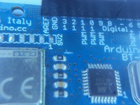
The ArduinoBT board with the TX line from the WT11 cut
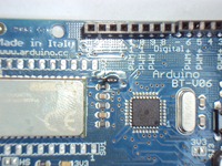
Tracing the WT11’s Tx line on the board (found from the datasheet), I made a small cut in the trace using an exacto knife. I then scraped away solder mask on the trace and soldered a 3.3kohm 0603 resistor inline. This would allow the WT11 to send data to the ‘328, but would allow an external UART to be connected too. The external UART takes precedence, since it is directly connected to the ‘328 without a resistor.


Left:Too much flux never hurt anybody Right:after a quick iso-proply cleaning
The ‘new’ board is working fine, and the bootloader, if really required, can be reverted to the original.