Those of you who are acquainted with my eccentric mannerisms must know that I rarely throw junk out, more so if it is electronic scrap. Old electronics are perfect places to find serial memory chips and audio amplifiers and digital logic gates and motor drivers. Sometimes (well, actually most times) the chips have vague numbers and markings, or even no numbers (so as to protect the manufacturer’s IP) and are therefore, quite unusable. You see, I be trawlin’ fo’ gold in the bogs, ya scallywags! And very often I pick up scum. Occasionally the chips are variants of common chips, and a bit of googling (funny how that term’s become a verb over the last few years, no?) turns up suitable datasheets. Other times the chip is just obscure enough to have a presence on china-ic-mart.com, but not have a datasheet. Even a Digikey search results in seeming useless information. However, if you’re willing to try to emulate Sherlock a bit then you can find similar devices with similar specs and similar pinouts.
The key word here is ‘similar’. If you’re *very* lucky you get the right pinout, but if Murphy is to be believed, its more likely that D0 will actually be Q1, and Xtal will really be Vin.
In the old days I would search for the closest matching chip for which a datasheet was readily available and have a go at the unknown chip. I would spend painfully long hours hunched over a chip with a multimeter in one hand, an oscilloscope probe in my mouth, and a finger on the chip-under-test, to ensure that it wasn’t overheating because of a reversed Vcc-Gnd.
A simple tool that allows you to sidestep this agony is the Bus Pirate. Developed by Dangerous Prototypes and marketed by Seeed Studio, this a fantastic tool that’s great for the intrepid hacker. It’s got several useful modes that allow you to bombard the device under test with different protocols until it finally burps out some info. Ordinarily, I would sit and program a microcontroller to ‘talk’ to the DUT. This would be a hit-or-miss kind of thing as I wouldn’t be aware of the DUT’s communication protocol. Since a lot of industrial protocols (like asynch serial, I2C, SPI and OneWire) as well ‘raw’ protocols are already built into the firmware of the Bus Pirate, you can save a lot of time and effort in your quest to unravel the chip’s mysteries.
So I’ve been wanting to get myself a Bus Pirate for quite a while, but its been out of stock at Seeed Studio for ages! DP has cool “Free PCB” days where they give out free PCBs (duh!), including Bus Pirate PCBs, but I’ve never been lucky enough to snag one. I got sick of waiting my turn and finally decided to build one myself.
And what better stuff to build the Bus Pirate from than the very junk that its going to be used to test! Most of my Bus Pirate’s components are salvaged from old computer motherboards, CD ROM drives, and an old Motorola phone (thanks Eeshan – I got funky blue LEDs!). The board is an unhealthy mish-mash of through-hold and SMD components.
Changes
I’ve made a few tweaks to the original BP design, substituting the voltage regulators with what I had lying around – an LP2950-3.3v in an easy-to-solder TO92 package powers the BP, while SOT23 REG101s provide 3.3v and 5v to the external devices that the BP is capable of powering.
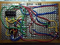
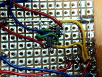
Left: The bottom of the board.
Right: A closer look at the regulators. I didn’t even bother adding filter capacitors on the outputs; maybe I will later.
Since I had a Sparkfun FT232RL breakout board, I used that for comms (instead of having the FTDI onboard like the original).
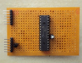
Pin headers, the LP2950, a PIC24FJ64GA002, and a capacitor are on the top.
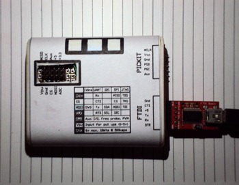
The top of the board. Visible are right angled pin headers (the top left one is for a PICKIT programmer, the bottom one is for the FTDI). Beside the
I also had a SOIC14 MC14066B from an old motherboard that I used in place of the CD4066.
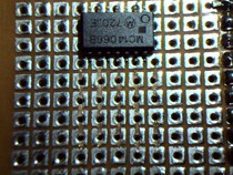
 Left: Prepping the 4066 for soldering onto veroboard. Each pad was cut in half.
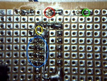
Right: some SMD components – 10kΩ voltage dividers for the ADC in blue; 470Ω for LED current limiting in green, a 0.22uF ceramic in the yellow circle, and the blue LEDs in red.
A few cosmetic changes, like blue status LEDs, and juggling the BP header pins about, were also necessary; but the general idea remains unchanged.
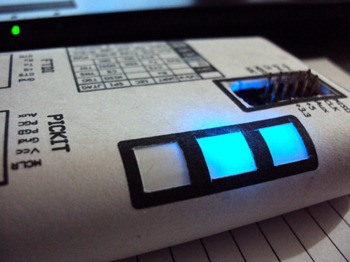
The ‘Power’ and ‘Mode’ LEDs lit up. I forgot to name the LEDs on the paper decal.
The case is an artificial sweetener box swiped from mom’s kitchen and repurposed with my Dremel. Slots were cut into either end to hold the veroboard in place. An opening was cut in at the top, allowing the header to poke out. Two smaller openings were made for headers to the FTDI and a PICkit2.

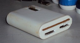
Left:The original case, and Right: after being sanded and cleaned.
Once built, I programmed the PIC24FJ64GA002 with my trusty PICKit2. Firmware v5.10 was uploaded using ds30Loader. My BP passed the self tests without so much as a whimper.
To try out its features I decided to continue fooling around with the BU2090.
Driving the BU2090FS with a BP
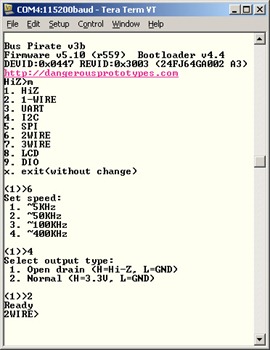
Configuring the BP was simple enough. When I was greeted with HiZ> on the main prompt I changed mode to 2WIRE by pressing m and then 6. I pressed 4 to get the fastest available speed – 400kHz, and made the outputs ‘normal’ by entering 2.
It was now a simple task entering special characters (_ – / \) to toggle the DATA and CLK lines the way I wanted.
The ‘2090 shifts one bit of data at a time.
To shift in a ‘0’ the keystrokes used by the BP are: _/_\.
To shift in a ‘1’ they are: –/_\.
Once data is shifted in it needs to be latched to the outputs.
To shift in a ‘0’ and latch all the data (including the recently shifted bit):_/-\.
To shift and latch a ‘1’: –/-\.
So if I wanted to get the following binary output from the 12-bit output of the ‘2090: 1 1 0 1 0 0 0 0 0 1 1 1, I’d use the following syntax:
–/_\–/_\_/_\–/_\_/_\_/_\_/_\_/_\_/_\–/_\–/_\–/-\
1 1 0 1 0 0 0 0 0 1 1 1L
MSB LSB
I’ve depicted alternate bits in different colours for clarity. Data is left-shifted MSB-first. The last ‘1’ to be shifted in latches data to the outputs. A quick video of data being shifted in is on it way, but you’ll have to make do with a still for the time being.
Of course, this may not be the most efficient way to control the ‘2090 with the BP; there may be shorter command sequences, and better modes. Please post in the comments if you know of a better way.

No comments:
Post a Comment