Wednesday, October 14, 2009

Scrounging Around…….

This post is similar to one I had made on BITS 360 a while back. Having finished my Bachelor’s degree from BITS-Goa, I’ve now transferred to the Pilani Campus. So this is my first post after coming to Pilani.

As was in Goa, here too several ‘poor’ students (a point to note is that the word ‘poor’ refers to the usual scarcity of money that college students, being college students, face, and not an actual financial constraint :-D) wanted to know where they could cheaply source components. Obviously, I feel it my moral obligation to provide scrounging references. Read on to find out where I usually source a large part of my components.

Some excellent sources for jugaad are mentioned below. The list format is -
"Old electronics - many students throw out...."
"You will be able to scavenge...."

  • UPS systems
    buzzers, relays, power transistors, resistors, SRCs, triacs, massive heatsinks, even more gargantuan transformers (these are bl**dy heavy), awesome lead acid batteries (be warned, a faulty lead acid battery may be the very reason for the UPS' demise :-/ )

  • Electronic ballast tubelights (the new kind of 'slim' tubelights), CFL bulbs (I find loads of faulty ones in BITS - just ask the electrician, he'll only be too glad to get rid of them!)
    Ferrite chokes, thick wire to make air core inductors, high voltage capacitors, diodes, SRCs.

  • Alarm clocks (I don't really know how these get damaged...most BITsians claim that they fell down, or someone sat on them - I personally think they were chucked at the wall when they woke their owner up too early in the morning! ;-) )
    High pitched buzzer / speaker, 32768KHz crystal, tiny gears

  • Keyboards, mice (optical and ball), CD/Floppy drives, other PC junk
    JACKPOT!!! - buttons, leds, capacitors, optical sensors (optical mice have a very cool 18*18 pixel CCD - Google ADNS2610; anyone looking for advice or interface details, buzz me, I've done this), motors, heck maybe even a working 12 / 5 / 3.3V SMPS!

  • Phones (the traditional telephones, and newer cellphones)
    Magnetics, audio stuff. Mobile phones are a veritable source of ultra-small components: you need a steady hand, an SMD rework station, and guts of vanadium-steel to take these babies apart. I've used LCDs, very powerful white LEDs, joysticks, memory card connectors, buttons, etc from (discarded) mobiles. Most Nokias use the BL5C / BL4C - this is an uber-cool LiIon (old) and LiPoly (new) flat battery, 3.7v @ 700-1200mAh. I've drawn 15Amps from this thing for 60sec! No kidding! My multimeter leads got hot and one of the tips actually melted. I would not recommend doing this at all - you may damage the battery irreparably, and worse still risk explosion-caused burns (remember the Nokia battery-replacement drive a couple of years back?). Still, the BL5C is very good for small bots and compact electronics. You can get it for 750 bucks (original) or 120 bucks (cheapo duplicate). The duplicate seems to work fine, but test it out before buying.


While the phrase “one man’s junk is another man’s treasure” fits aptly, be warned that scavenging can be time consuming and the components obtained from the abovementioned sources can be unreliable. Having issued my warning - good luck, and happy scrounging!

Sunday, July 5, 2009

To Do

If I remember correctly, my first introduction to circuits was in my 4th grade when my dad’s friend gave me a neat science-projects like kit. The kit contained components to teach the basics of electronics - switches, a buzzer, small incandescent bulbs (I absolutely dislike using these bulbs nowadays because of the power they drain), wires, steel wool, and other such things.

I was in the US at that time, and Lucas, a friend, and I, used to perform the ‘experiments’ given the handbook. I don’t know what Lucas’ dad did exactly, but to me he was some sort of god; he had tons of toasters and mixers and radios and TVs and machines lying open in his house. My mom would definitely have hit the roof had she seen such an untidy house. But I loved that house because, I suppose, it contributed a lot towards encouraging me to explore electronics as a hobby. And would you believe I’ve still got components from that kit!

In the 6th grade I read something about an FM transmitter and pestered my mum to take me ‘shopping’. I bought a couple of condenser mikes and speakers, but not knowing anything about transistors and chips, got absolutely nowhere. I did, however, manage to build a working crystal radio – very interesting things, I must say.

I always loved mechanics, and continued tinkering with small motors and toy cars and bulbs till the 10th grade. Finally, when I moved to junior college, I got my first formal introduction to electronics. I had loved the mechanical aspect of things, and could put my hand to anything that had gears and rods and levers. So junior college, with its electronics, was a new experience.

Every year I keep growing in experience and exposure, and my ‘To Do’ list keeps expanding. There are a lot of things that I want to build, but I’ve either not had the time or the knowledge to see them through. A lot of the things in the list are half complete; some of them have passed the proof-of-concept stage and are awaiting, to borrow from software lingo, the transition from beta to release version. Summer break is the perfect time to hit these projects with a vengeance, and I certainly plan to achieve a lot during these two and a half months.

The only problem – as I’m researching one project I invariably come across something new and attractive, which but naturally, gets appended to the To Do list, making it longer still!

Here’s my list, in current form:

Project Status
Linear PSU v3; Revision required
SMPS Proof-of-concept
Home Energy Meter To be done
Air Conditioner Controller v1; Revision required
Computer Controller DMX To be done
Ultrasonic Rangefinder Proof-of-concept
Digital LC Meter To be done
Temperature Controller for Soldering Iron Proof-of-concept
Long Range Walkie Talkies To be done; (searching for info)
Home Intercom Using Old Phones To be done
Drill Press To be done (currently collecting parts) 
CNC Milling Machine To be done (currently collecting parts) 
iTrip Mod v1; Working
iPod Mini Remote To be done
Auto-balancing Inverted Pendulum To be done
PIC to VGA To be done
Optical Mouse Based Navigation System for Small Robots Proof-of-concept
Very Long Range IR Transmitter Proof-of-concept; (currently collecting parts)
USB PIC Programmer To be done
Class D Audio Amplifier v1; Revision required
Digital Weigh Scale To be done
Low Cost USB Oscilloscope Proof-of-concept
Nokia 3310 / 6610 LCD Interface Proof-of-concept
CYUSB6934 Radio Interface Proof-of-concept
Lightweight Multipurpose Robotic Platforms (to be christened ‘Saxiest’ :-D ) v2; Revision required (currently collecting parts)
Foot Speed Controller for my Dremel XPR To be done; (searching for info)

As you can see, several projects still need to be started. Any advice/help/experience is most welcome :-)

Friday, July 3, 2009

The Super Probe

I remember mentioning in one of my earlier posts that an Oscilloscope was very high on my wish-list. The other day I entered into a bidding war on eBay-USA for a no-name DSO. It was pretty inexpensive, and the features it had seemed reasonably good. Sadly, I was outdone by some chap from Germany, who was willing to pay more than four times the amount I was.

After the eBay misadventure, my electronics toolkit continued to remain woefully incomplete. Apart from a simple multimeter and the PICKit2-Logic Analyser, I lacked the resources to take essential circuit parameter measurements – frequency, event counting, capacitance, inductance. I would also like a function/signal generator which would be able to output a PWM signal, pulses, pseudo-random number sequences and such like. Was there a multipurpose, do-it-all out there that would enable me to do all of this without breaking a bank?

About two years ago I had chanced upon the Super Probe while googling for a low cost capacitance meter. The Super Probe, designed by Luhan Monat, is a DIY low-cost and very low parts-count tool. As its name suggests, the Super Probe is capable of taking a variety of measurements with a fair degree of accuracy. It can also be used to output some useful waveforms and signals.

When I first saw Luhan’s site, I built a solderless-breadboard-prototype for myself. It lasted all of three days before the rats-nest of wires and components was deemed unsightly and cumbersome, and was relegated to the corner of my room, before being cannibalised for parts. I’ve finally gotten around to building my self a ‘proper’ Super Probe – the ensuing photos are ‘proof’' :-)

1 

My 'Probe is enclosed in an old Orpat ODM-100 Multimeter case. I ripped out the insides (naturally keeping some of the components – the LCD, and some precision resistors – for future projects :-D ), replacing them with my own circuits. The entire 'Probe is built on proto board using DIP components. I plan to design my own PCB later with SMD parts.

Using my Dremel XPR400, I cut a slot in the side of the old multimeter to accommodate an ON-OFF slide switch. A circular piece of acrylic was glued in place of the rotary switch of the multimeter. Openings were also cut for buttons, which were ‘borrowed’  from an old non-functional calculator. Both, the button holes, and the switch slot, were made using the etching bit of the Dremel. To make the circular acrylic piece, I started by trimming the sides of a square piece. I drilled a small hole in the circular-ish piece and mounted it on a mandrel. This setup was spun at about 20,000RPM on a rough file till a circular shape was achieved, and then on a smooth file for finishing. You could just as well use a lathe to do this, but I had to make do with what tools I have :-( The circular acrylic piece was super-glued into place, as was the slide-switch.

The images below, from left to right, are of the slot cut for the switch; the switch glued from the inside; and, the modifications made to accommodate the buttons.

There are four PCBs inside the multimeter case – the display board, the actual 'Probe, a button mount, and a 7805 regulator. The reason I used a ‘modular’ approach is for ‘upgradeability’. Yeah, yeah, don’t laugh! I’ll tell you how ‘upgradeable’ this device is – I plan to replace the just PCBs with just one, which integrates everything. But until the time I actually design and etch the integrated PCB (I use the toner-FeCl3 method, and I no longer have access to a good laser printer) I would like to tinker and test the individual circuits. Each time I fiddle with a certain sub-circuit, and I wouldn’t want to build a completely new 'Probe.

inside2insides

The PCB wrapped up in red electrical tape is the 7805. The tape was necessary to prevent shorting. In the second pic, the crystal, wrapped in black electrical tape (also to prevent shorting) is visible.

For example, tomorrow I’m going to swap out the power-hungry and inefficient 7805 regulator with the much nicer, and comparatively power-thrifty MAX1836 buck converter from Maxim. I’m currently running off a 9v PP3 battery. With the 7805, I’d get 5v on the output as long as the PP3 voltage is above 7v. Current draw by the circuit is 20mA peak and about 10mA average, so with 9v on the PP3, I’d lose clip_image002[9]across the 7805. With 7v, I’d lose 20mW.

Now, although this doesn’t seem like much, I could improve battery life tremendously by using a buck regulator which is near about 85-95% efficient. So I’d reduce the power lost across the regulator to about 8mW – a reduction in power loss of 80%. Another advantage of Maxim’s 1836 is that it allows me to run the PP3 down to 5.5v, and it will still give me a nominal 5v on its output.

Back to the construction. For the display, I used individual 7 segment LED displays. The original 'Probe uses a 4-digit multiplexed display, but individual display blocks can be used as well, though soldering them is one hell of a pain in the butt (literally! Hehe :-D ). I put a sheet of cellophane paper (plastic) on top of the display to improve contrast.

The 'Probe uses a PIC16F870 as its brain. Luhan has been kind enough to provide a pre-complied HEX file which only needs to be burnt onto the PIC. He’s also provided the source code for download so you can modify the code as per your needs.

The Super Probe does have its limitations. It certainly is very inexpensive; the caveat is accuracy. The device’s readings are only as reliable as its components. Measurements should not be taken as God’s Word and whenever possible, must be checked against standard tools.

Anyway, the 'Probe has rapidly become one of my most useful tools. Of its 17 functions, I use the Frequency Counter, Event Counter, Servo Pulse Generator, Square Wave Generator, PWM Generator, and 38kHz IR Pulse Generator most often. For a list and description of all its functions look at the list below or visit the Super Probe website.


Super Probe Functions
Logic Probe – High, Low, Tristate
Logic Pulser with variable pulse rate
Autoranging Frequency Counter
Event Counter
Voltmeter 5v max.
Diode Junction Drop
Capacitance Meter
Inductance Meter
Signal Generator – 0.5v, 500Hz square wave
NTSC Video Signal Generator
Serial ASCII Generator – selectable baud rates: 1.2/2.4/4.8/9.6K
MIDI Note Generator
Hobby Servo Pulse Generator
Square Wave Generator – 1 to 9999 Hz
10kHz Pseudorandom Number Generator
38kHz Generator – useful for testing IR receivers
PWM Generator – 3 to 97% duty of a 6kHz square wave

Thursday, May 28, 2009

Tripping Up?

About two years ago one of my best friends (I’ve known him since the 9th grade in school, and we were in JHC, A-Div together) gifted me a Griffin iTrip. He had just recently bought (been gifted?) an iPod video, and the iTrip 4014 was not compatible with it. Not wanting to throw the iTrip out, he very sweetly gave it to me (thanks bro!).

Incidentally, I happened to be the second in our ‘gang’ to own an iPod, after another one of my best friends (c’mon, I can have more than one best friend! As a matter of fact I happen to have 15 at this moment). He had a silver Mini, and we would take turns listening to it in the electronics lab, while we soldered away at a 7447 and a 7490 counter-with-display circuit.

I take a teensy moment now to salute my alma mater – Jai Hind College. JHC, was an oasis in a concrete jungle, ‘figuratively’ speaking (wink, wink :-)). Just off Marine Drive in Bombay, JHC was where I did my junior college. I studied Electronics as a vocational subject and was taught Sam’s Laws, by none other than Prof. Samel, who also taught us other important things, such as the reason Darlington pairs are named so (Note to reader: if you are opening your eyes in bewilderment – ‘what is he talking about?’ – you are pardoned; this is an internal joke). Coutinho, Rane and Bai were the ‘awesomest’ of teachers!

Right. Back to the topic at hand. I used the iTrip with my iPod Mini a couple of times before keeping the iTrip aside in disgust because it used to drain my already weak battery super quick. Earlier iPod batteries had notoriously short run times – only 4 hours for a new Mini; these days, play times of over 20 hours are not unheard of! One mod I made to my Mini was swapping out the Hitachi Microdrive, and replacing it with a CF card. By the time my iPod got ‘old’ enough for me to gather the courage to disassemble it, my Li-Ion battery was too far gone to make any real judgment about the modded performance. However, in all fairness I must say that I did notice marginally improved battery life (the CF card has no moving parts as opposed to the spinning platters in a Microdrive, so battery juice lasts longer), but nothing that merits boasting.

I am, at some later date, planning to strip down a Nokia BL5C and replace the original Mini battery. Why go through all of this trouble when I can simply buy a new Mini battery online? Well, for one, at the time of writing this replacement batteries (USD 30) are horrendously expensive compared to a BL5C (INR 125; ~USD 3); Apple charges a bomb (USD 75) to replace the batteries themselves; and lastly, I’m doing it just BECAUSE I CAN :-)

The iTrip 4014 is an FM transmitter that is capable of transmitting from 76 MHz to 108 MHz. Based on the BH1415F from ROHM, it also has a PIC12F626. The frequency at which the iTrip broadcasts is set by the '629. Small sound clips (provided by Griffin) are to be played by the iPod to change the frequency. The clips contain codes which tell the '629 which frequency to set.

Sadly, the iTrip 4014 can only be used by an iPod, and that too, only from its remote control port. Naturally, I did not like this forced restriction. So I decided to see if I could mod the iTrip to play from any old source with a 3.5mm jack.

I trawled the net for pinouts and specs, and came across several tutorials to increase the transmission range, but none that told me how to make the desired modification. 
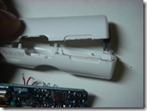
This site came close, but a different iTrip was used. Anyway, I took apart the iTrip with a sharp craft blade. You can see the scuff marks at the bottom – these are the only visible signs of damage to the case (which I plan to discard anyway).


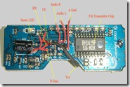
After a bit of poking around and with some intuitive guesswork I figured out which wire went where and did what. The images are marked with the relevant data incase you decide to take your iTrip apart. The image on the right has the microcontroller (a PIC12F629) and the one on the left has the FM chip (BH1415F). Click on the image for a better view.


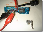
I rigged a rough setup to power the iTrip externally. In the image below, my trusty PICKit2 is providing 3.3v to the iTrip. Also visible is the connector which plugs into the remote control port at the top of the iPod. The image to the right is a close up of the connections.


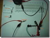
The audio jack was connected to my laptop, and audio was broadcast to my radio. It worked perfect. The ultimate aim is to make this into a standalone FM transmitter, therefore to change channels I would need some way to provide the audio control commands to the iTrip.

The audio commands are extremely simple – they follow an ASK-like format. A command is 19 bits long, and is transmitted LSB first to the Audio L wire (it’s the tip on the 3.5mm jack). A sample audio command clip being analyzed in Goldwave is shown below.

5

To switch frequencies the user plays a command file (which sounds like random beeps), pauses it after the ‘random’ beeps, waits for a few seconds till the iTrip automatically locks the frequency, and then resumes playing audio. The first string of blips is the actual command to switch to 107.7 MHz. The three blips towards the end mean ‘Ignore the previously issued command’. This is to prevent inadvertent frequency switching incase this file is played when the player is in ‘shuffle’ mode. In case the file is played by mistake, the iTrip will receive the command beeps, try to lock the new frequency, then receive the ‘ignore’ beeps (since the user would not have paused midway) and not lock to the new frequency.

6

7


The 19-bit command is (LSB first) ‘1010 10101100001 1001’. A command is framed by ‘1010’ to the left, and ‘1001’ to the right. The actual command word itself – ‘10101100001’, if read right to left is ‘10000110101’, which happens to be 1077 in decimal. Divide that by 10, and you get the FM frequency, 107.7. The ignore command is just ‘10101’. Each ‘1’ is 20ms of a 1000Hz sine wave. Thus each ‘1’ consists of 20 peaks and 20 troughs. A ‘0’ is just 20ms of silence. The commands are fed to the PIC, which decodes them, and sets the desired frequency.

Some commands are given below:

Freq.

Decoded Audio

Frame

Data (LSB first)

Frame

Data (MSB first)

Data in decimal

76.0

1010000111110101001

1010

00011111010

1001

01011111000

760

76.1

1010100111110101001

1010

10011111010

1001

01011111001

761

76.2

1010010111110101001

1010

01011111010

1001

01011111010

762

76.3

1010110111110101001

1010

11011111010

1001

01011111011

763

76.4

1010001111110101001

1010

00111111010

1001

01011111100

764

76.5

1010101111110101001

1010

10111111010

1001

01011111101

765

76.6

1010011111110101001

1010

01111111010

1001

01011111110

766

76.7

1010111111110101001

1010

11111111010

1001

01011111111

767

76.8

1010000000001101001

1010

00000000110

1001

01100000000

768

76.9

1010100000001101001

1010

10000000110

1001

01100000001

769

77.0

1010010000001101001

1010

01000000110

1001

01100000010

770

93.0

1010010001011101001

1010

01000101110

1001

01110100010

930

96.6

1010011000111101001

1010

01100011110

1001

01111000110

966

105.6

1010000001000011001

1010

00000100001

1001

10000100000

1056

108.0

1010000111000011001

1010

00011100001

1001

10000111000

1080

To figure this scheme out I had to open multiple files and compare the data. Here’s a shot of my desk. Notice the dual screens :-). iTrip open heart surgery is in session.

8

So this got me thinking – more likely than not, the PIC was simply ignoring the fact that the signal was a sine. It could work just as well with a square wave. And I could provide a square very easily with another microcontroller.

As a proof-of-concept experiment I generated the square wave in Goldwave (image-left), and created an audio clip similar to the command file (image-right).

9 10


I played this to the iTrip, and it switched frequencies like a charm. I can easily program a PIC to poll a couple of buttons, provide the requisite string of square waves when a button is pressed, and display the changed frequency on an LCD/numeric LED, thereby giving me a standalone FM transmitter.

Sites that were useful / will be useful:
http://badacetechshow.com/psp_itrip.htm
http://www.maushammer.com/systems/ipod-remote/ipod-remote.html
http://stud3.tuwien.ac.at/~e0026607/ipod_remote/ipod_ap.html
http://nuxx.net/wiki/Apple_Accessory_Protocol
http://www.petertyser.com/2005/04/28/motion-based-ipod-remote-control/

Future plans:
1. Make it into a standalone transmitter with button-selectable frequencies.
2. Provide power from a tiny rechargeable Li-poly. This would entail making a charger circuit (for recharging), and a buck regulator (to provide 3.3 volts to the hacked iTrip).
3. Make a nice enclosure.
4. Boost range/power.

Stay ‘tuned’ for future updates! :-)

Wednesday, May 27, 2009

After the Long Break

I haven’t blogged for aeons! It’s been around six months since I last blogged. So much has happened in these six months. I am now an engineer – BE Mech. It feels good. My last six months in college (BITS – Goa) were an absolute blast! Quark, Waves, Spree, all in one semester! Walkie-talkies for backstage members was fun :-) . I made a bunch of new friends, and came closer to those who earlier happened to be just acquaintances. I learnt (and started using) a load of very weird sounding slang (which, mind you, is unique to BITS – Goa). Some BITSian slang, in their (hopefully correct) usage are noted below, and, while a few may be common in other parts of India, I assure you, each phrase has multiple meanings, many of which I have not been able to list here.


In BITS, BDM, Pinky, Shalini, Aruna & Co. would be pleased and proud (NOT!!) with our attempt to include classroom grammar rules in daily conversation. Naturally ‘lol’ becomes ‘loler’; and if you find the ‘zoke’ very funny, you’d say ‘lolest’. Very very funny would be ‘lolest-est’. It is obvious…oh! sorry – it is ‘ob’ that such grammatical extrapolation can be used for other words – ‘ob’, ‘obber’, ‘obest’, ‘obest-est’? If you find this tiny task in English tough, then you’d surely be ‘raped’ in our examinations. You’d probably come out saying ‘Damn! Paper ne phaad di. Rapest paper!’ Or maybe, ‘paper ne f*ck maar diya’? The sad thing is, that in BITS, exam ke samay life mein f*ck ho rakha rehetaa hai.


If you are one of the chosen few who manage to turn the tables on the paper then you are ‘proest’. You’d go around the campus shouting ‘backslash-m-forwardslash’! ‘backslash-m-forwardslash’ or ‘Yaar, life mein sex ho rakha hai’! Otherwise, by the second paper most people take it lite (light). A friend of mine once commented upon the marvelous way these two phrases – ‘life mein f*ck ho gaya’; and ‘life mein sex ho gaya’- actually mean the same, an yet are completely opposite in terms of how they are used.


Regardless, by the third paper, if lite has not been taken by you, then tum noobism kar rahe ho; faaltu mein apni maraa rahe ho, kyunki abhi tak toh sabka ‘gg’ ho gaya hai. Finally when you get your corrected papers, the only excuse you can make to your parents is “Mama, lol ipoindi. But chintaa mat karo, baaki sab ka bhi ‘gm’ hua hai, in other words, sab ne m2l2”. ‘m2l2 (right here I was facing this dilemma – should I capitalize the ‘m’ in ‘m2l2’ since it began a new word/acronym after the full-stop? I decided against it, since the quandary I would be in next would be the issue of capitalizing the ‘l’ in ‘m2l2’ – I’ve upper-cased the ‘m’, so to maintain an evenness, it would only be right to upper-case the ‘l’. But then that might distort the acronym so much that this much loved phrase would be unrecognizable – M2L2. I say ‘much loved’ because I know that through careful cogitation people have extended this to m5l5 and even m6l6. I must point out that m2l2 actually started out as m2l2. It only changed into its present form to aid quick typing on DC main chat). DC is absolutely ‘ulti-mate’! Many chaps are called by their DC nicknames, rather than by their real names – Tillu, Rash, Achillies, Sid bloke. There are cases where people don’t know the real names of these people! If people don’t know your real name, then you simple have to take lite, and chill, machha!


Anyway, I am back home in Gurgaon now, and have a lot of free time on my hands. Just yesterday I met up with some really close friends – Prawn-soup and Sanso. We met up to hang out, and in the course of time, as most college-goers are wont to do, landed up at CafĂ© Coffee Day – CCD where Sanskriti had the following conversation with the waiter:


S: Could I please have the chocolate cake?

W: Chocolate cake?

S: Yes, please.

W: Anything else?

S: No, thanks, that’s it (big Sanso-smile)

W: Would you like it with warm?

Sanso, Pranshu, Rohit (to themselves): What the …?

(aloud): Umm, excuse me?

W (louder and slower, as if that would help!): Would you like it w-i-t-h-w-a-r-m?

R: Oh, you mean would we like it warmed?

S: Aah yes! (Bigger Sanso smile)

R: maybe we could ask the waiter to give us a portion of ‘warm’ in a separate dish? Maybe with two spoons? :-P


I am presently taking apart my iTrip from Griffin. Next blog topic: Cool iTrip mod.

Visitors